|
|
|

 |
|
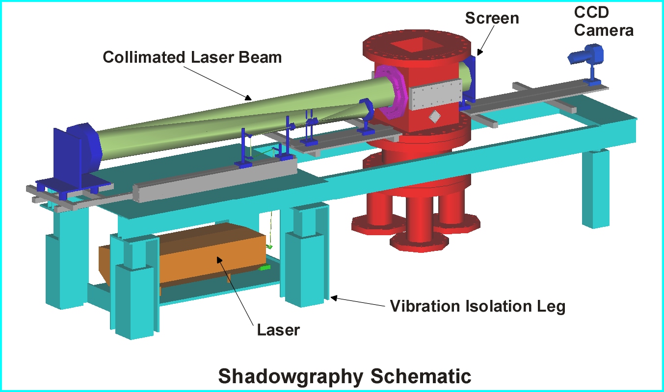
Pressure and Imaging DiagnosticsPiezoelectric pressure transducers are flush-mounted along the wall of the shock tube for determining shock speed and for triggering the pulsed laser for imaging. There are two types of imaging used in the shock tube, through-field imaging (shadowgraphy and Schlieren) and laser sheet imaging. An example of the shadowgraphy setup is shown below.
The laser is pulsed at a preset delay time based on the shock strength to image the interface through the test section. The laser, optics and camera are supported by a vibration isolation table. The pulsed laser is steered through a series of mirror, expanded, and then collimated and goes through the test section onto the screen. The screen is imaged with the CCD camera and then stored on a computer. With through-field imaging density gradients (with schlieren) or the gradient of a density gradient (shadowgraphy) appear as dark areas on the screen. Thus, a planar shock being a thin steep density gradient appears as a flat line on the screen. This technique also captures a Richtmyer-Meshkov unstable interface as the interface itself is a density gradient between two gases. Typically a CCD camera with a 1024x1024 pixel array is used to capture a high resolution image.
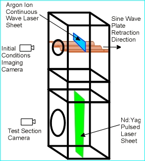
The laser sheet imaging setup is shown to the right. In the schematic there are actually two laser sheets shown, one in the interface section and one in the test section. The retractable sine plate is shown in the interface section. For this experiment, the initial conditions are imaged real time with a CCD camera (either 256x256 or 532x516 pixel array) framing at 100-200 frames per second. The argon ion laser beam is steered with mirrors for a 488 nm wavelength and enters through a port in the side of the interface section and illuminates a 2D slice of the interface at the center of the square cross-section. The camera catches 10-200 frames of the developing interface (depending on the gas pair used) before the shock wave accelerates the interface down to into the test section. When the interface is in the test section, the Nd:Yag laser is triggered and emits a laser pulse that enters the shock tube through a window in the bottom flange. This laser pulse is steered with mirrors for a 532 nm wavelength and the test section camera has a 532 nm filter to keep any stray reflections from the other laser from being imaged on the CCD. Unlike in through-field imaging where density gradients are seen, in planar imaging it is necessary to scatter light from the interface into the CCD camera for visualization. Light scattering can occur off the molecular species (Rayleigh scattering, a weak signal) or by seeding one of the gases with smoke or a fluorescing molecule. |