Experimental microelasticity of two porous solids
A Cosserat solid with more freedom than classically elastic solids
Adapted from
International Journal of Solids and Structures 22. No. 1. pp. 55-63, 1986.
Bottom: recent article on this material
Abstract
Experiments are performed to determine the dependence of torsional and bending rigidity upon diameter for rod-shaped specimens of dense polyurethane foam and syntactic foam. Results show an effect due to the microstructure. Size effects are observed in the linear regime of small strain. Results are describable by a Cosserat elastic model. The six Cosserat elastic constants are determined.
Remark
Couple stress theory is a special case for κ tending to infinity, much larger than the shear modulus. That corresponds to N = 1. The present experiments show weak coupling, N = 0.2, therefore exclude both classical elasticity and couple stress elasticity for this material. Modified couple stress theory is also excluded.
Download pdf of this article.
1. INTRODUCTION
Materials with microstructure may possess degrees of freedom in addition to those of an ideally homogeneous medium. Efforts to incorporate some of these degrees of freedom in continuum theories include the landmark 1909 monograph of the Cosserat brothers [l], as well as more recent articles by Mindlin [2, 3], Eringen [4] and others. In the Cosserat (micropolar) theory, the local rotation of points is postulated to be an independent kinematical variable not necessarily equal to the macrorotation determined from the gradients of the displacements. The corresponding dynamical variable is the couple stress, or couple per unit area upon a differential element.
The constitutive equations for an isotropic Cosserat solid are given as follows.
Classical elasticity is obtained as a special case by allowing the first four of these elastic constants to tend to zero. Few experimental studies which intend to explore the possible applicability of Cosserat and other generalized continuum theories to real materials have been attempted. In metals such as steel [5] and aluminum [6], experiments disclose purely classical behavior. A model particulate composite [7] intended as a possible Cosserat solid was also found to behave according to classical elasticity. Preliminary one-dimensional results [8] suggest a restricted form of Cosserat elasticity, couple stress theory, may apply to a polymeric foam. Human bone, a natural fibrous composite, displays size effects in torsion and bending which are consistent with Cosserat, rather than classical elasticity [9-l I]. Bone, however, is structurally and elastically anisotropic, which complicates its analysis. Recent study of a low-density polymeric foam discloses nonclassical effects which can only be approximately modeled by Cosserat elasticity; it appears that this material has additional micro deformational degrees of freedom, not included in the Cosserat theory [12].
The present paper is intended to experimentally explore the microelastic behavior of two dense isotropic porous materials.
2. MATERIALS AND EXPERIMENTAL METHODS
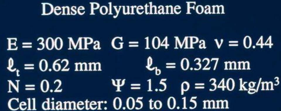
Two structured materials were examined. The first, a syntactic foam, consists of hollow glass microbubbles embedded in an epoxy matrix. The density is 585 kg per cubic meter, and the voids range in size from about 0.070 to 0.180 mm. The second material is a high-density rigid polyurethane closed-cell foam. Its density is 340 kg per cubic meter. The voids in this foam are from 0.050 to 0.150 mm in diameter. Foam microstructure is shown in Fig. 1.
Fig. 1. Top: Polyurethane foam, reflected light micrograph. Scale mark, 0.25 mm. Bottom: Syntactic foam, reflected light micrograph. Scale mark, 0.25 mm. See original article or pdf link at the top for these figures.
The basis for the experiments is the size effect predicted to occur in the torsion [7] and bending [13] of cylindrical rods of a Cosserat solid. Specifically, classical elasticity predicts that the torsional and bending rigidity of rods is proportional to the fourth power of the diameter; in contrast, Cosserat elasticity predicts that rods of small diameter will be more rigid than would be expected on the basis of the rigidity of a specimen of large diameter. By measuring both the torsional and bending rigidity of cylindrical rods as a function of diameter, it is possible to calculate all six Cosserat elastic constants of an isotropic solid.
Methods based on size effects have been used by others in attempts to investigate microelastic effects. These methods differ from the present approach in that [5] and [6] used one-dimensional techniques capable, at most, of revealing one nonclassical constant. Gauthier's approach [7] is capable of determining all six Cosserat elastic constants, but it requires at least two different kinds of specimens and three apparati: one for tension tests, one for torsion tests on rods, and one for bending tests on plates. The present approach makes use of the same apparatus for both the bending and torsion experiments.
Specimens were rough-cut on a bandsaw into a prismatic shape, and were turned down to right circular cylindrical form on a lathe. Specimen surfaces were finished on the lathe by means of cloths and papers impregnated with graded abrasives. Each specimen was tested as described below, and then machined to a smaller diameter and tested again. The length-to-diameter ratio was held approximately equal to five during this procedure. When the specimen diameter became sufficiently small, ca 2 mm, further machining was done solely by the abrasive method. Specimens as small as 0.3 mm in diameter could be prepared in this way.
This diagram illustrates the size effect method. For graphs for foam please see original article or the pdf (via the link at the top).
Experimental apparatus intended for such size-effect studies must admit specimens with a wide range of rigidities, and frictional errors which would obscure the properties of slender specimens must be eliminated. In addition it is desirable that the same configuration be used for both torsion and bending of the same specimen, so that apparatus calibration is identical for both. The apparatus shown in Fig. 2 meets these requirements. The torque is produced by the action of an electric current in a Helmholtz coil upon a permanent magnet cemented to the end of the specimen with a cyanoacrylate adhesive. The angular displacement of the specimen end is determined using a laser beam reflected from a mirror cemented to the specimen or to the magnet. Earlier we discussed the method of magnet calibration, and described an approach in which the laser beam was projected to a distant screen to determine the angular displacement. In the present study we use an interferometric method for angular displacement measurement. The laser beam passes through a Ronchi ruling, 300 lines/in., designated by A in Fig. 2; interference fringes thus produced are reflected from the specimen mirror and pass through an identical ruling located at B. The second ruling is located so that its line spacing exactly matches the spacing of the fringes in the laser beam at that point. As the specimen-end rotates, the fringe pattern moves, generating an oscillating light intensity behind ruling B. A light detector consisting of a photodiode, mounted behind a narrowband interference filter, transforms the light signal to an electrical signal. The filter passes only the laser wavelength and excludes room light. One fringe corresponds to 140 micro- rad. Resolution is 0.05 fringe or better. Typical torque and angular displacement waveforms are shown in Fig. 3. In the configuration shown in Fig. 2 the magnet torque is such that torsional loading occurs. To perform a bending experiment, the Helmholtz coil is rotated 90 degrees, and the rulings are correspondingly rotated.
Fig. 2. Experimental apparatus.
Fig. 3. Oscilloscope trace for a dynamic experiment at 10 Hz. Top: Fringe signal for angular
displacement determined interferometrically. Bottom: Voltage across feedback resistor. proportional to the torque applied to the specimen. The phase shift between the torque and angle signals is due to viscoelasticity of the specimen, which differs from the ones discussed in the text.
The upper end of the specimen is cemented to a framework of half inch -diameter aluminum rods which also supports the laser and light detector. The framework is isolated from vibration by dampers consisting of three layers of soft foam alternating with 40 pound lead weights. One such damper supports each leg of the laboratory table which supports the framework. A similar damper isolates the frame from the table. The rigidity of the framework was found to be much greater than the rigidity of the largest specimens studied.
The apparatus is capable of creep, dynamic, constant-load-rate and resonance experiments, depending on the electrical signal input to the Helmholtz coil. in this study, dynamic experiments were conducted at several frequencies well below the resonant frequency; several creep experiments were also done. Specimen temperature was 22 deg C. The bipolar operational amplifier / power supply was prepared as a current amplifier, so that the coil current followed the driving signal from the function generator independently of any resistance changes which might occur in the coil. The voltage across the one ohm feedback resistor was input to the oscilloscope and chart recorder as proportional to coil current, hence to torque.
In the bending experiments the bending moment. due to the weight of the magnet, is a potential source of error. A correction factor was calculated, based on a simple beam-theory model. if the correction exceeded 1%, a smaller and lighter magnet was substituted. To ensure that no calibration error occurred. torsion tests on the same specimen using first the large magnet, then the small magnet, were performed. The results of these tests agreed to within 1%. The overall relative error in determining the rigidity is estimated to be 1% over the size range 1.4-9.6 mm. This is the size range used in the experiments on the polyurethane foam. For specimen diameters from 1 to 0.3 mm (syntactic foam) a larger error, ca 5%, is estimated for the rigidity. Most of this arises from uncertainty in the specimen diameter.
Two magnets were sufficient in the present experiments: a high-intensity samarium cobalt magnet of diameter 19.05 mm, thickness 6.4 mm and mass 14.93 gm, and a ferrite magnet of diameter 9.51 mm, thickness 2.96 mm and mass 0.998 gm.
3. RESULTS
Fig. 4. Size effect behavior of polyurethane foam. Rigidity/square of diameter vs. square of diameter. Points: experimental results at 0.1 Hz. Solid lines: best-fit Cosserat elastic theoretical curves. Dashed lines: classical elastic theoretical curves.
Size-effect results, plotted as rigidity divided by the square of the diameter vs. the square of the diameter, are shown in Figs. 4 and 5 in the original article.
T is the applied torque, z is the specimen length, and theta is the specimen angular displacement. These results are based on dynamic experiments at 0.1 Hz. The slope of the rigidity plot is the effective Young's modulus for bending, or the effective shear modulus for torsion. In a classically elastic material, these moduli are independent of specimen size, so the plot becomes a straight line through the origin. In a Cosserat solid, the form of the rigidity plot depends upon the six elastic constants. Theoretical plots are given elsewhere [12, 7].
Analysis and interpretation of size-effect results is facilitated by using the following' technical elastic constants:
Young's modulus E, Shear modulus G, Poisson ratio nu (dimensionless);
Characteristic length, lt torsion (m); Characteristic length, lb bending (m); Coupling number N (dimensionless); Polar ratio psi (dimensionless)
Cosserat constants
The above Young's modulus E has the same meaning as in classical elasticity in the case of a simple tension test [7], in which there are neither microrotations nor couple stresses.
Figure. Size-effect behavior of syntactic foam. Rigidity / square of diameter vs. square of diameter.
Points: experimental results at 0.1 Hz. Solid lines: best-fit Cosserat elastic theoretical curves.
Dashed lines: classical elastic theoretical curves.
In bending, if the rod diameter greatly exceeds the characteristic length l, the rigidity becomes indistinguishable from that of a classically elastic rod of modulus E. The characteristic lengths govern the specimen size scale, at which deviations from classical elasticity, e.g. stiffening effects, begin to be observed. For example, to observe a 10% stiffening, the specimen diameter must be about 16 times the characteristic length [7]. Analytical studies of materials with idealized structures predict that the characteristic lengths should be comparable to some length scale associated with the microstructure. The coupling number N, which can have values between zero and one, determines the strength of coupling between the displacement and local rotation fields. The case N = 1, for which many Cosserat effects are predicted to be maximum, corresponds to the "couple stress theory" [14, 15].
The results for the polyurethane foam (Fig. 4) are consistent with the following technical elastic constants: G = 104 MPa, torsion characteristic length = 0.62 mm, N squared = 0.04 and psi = 1.5 for torsion; E = 299.5 MPa, bending characteristic length = 0.327 mm, N squared = 0.04 and Poisson's ratio = 0.44 for bending. The residual error, defined as the sum of the squares of the deviations between the experimental and theoretical values, is as follows, in scaled units of (kN) squared for torsion, 0.5287 using the above Cosserat model, and 91.16 using a classically elastic model; for bending, 5.697 Cosserat and 58.59 classical.
In the present method the torsion and bending data must be internally consistent for a single set of six constants to adequately describe the data. For example, E and G may be used to calculate nu as in the classical case, and the shape of the bending theoretical curve depends upon nu. In addition, the torsional and bending characteristic lengths determined from the offset between the best-fit curve and a line of the same slope through the origin, determine beta and gamma uniquely. The ratio beta over gamma, however, governs the shape of the bending curve in the vicinity of the origin. Only for the values 1 and 1 does the theoretical bending curve pass through the origin. The coupling number N influences the shape of both the torsion and bending theoretical curves. Specifically, for psi = 1.5, its maximum thermodynamically permissible value, N governs the maximum apparent stiffening of thin specimens in torsion. Similarly in bending, for beta / gamma = 1 or -1, the extreme allowable values, N has the same effect. For psi less than 1.5 and for beta / gamma between -1 and 1, the limiting stiffening effect for small specimen diameter can become large in torsion and bending, respectively, even for small N. Physically, arbitrarily large stiffening effects are not to be expected, since any continuum theory will break down if the specimen size becomes equal to or less than the structure size.
Nevertheless, maximum stiffening effects of a factor two have been observed in thin (1 mm diam) specimens of human bone [10, 11], and a factor 3.5 in 0.6 mm diameter microsamples [16]. The maximum stiffening effect, i.e. the ratio of the rigidity of a thin specimen to the rigidity expected based on a classical elastic analysis using data from thick specimens, is about 30% for the present polyurethane foam.
For the syntactic foam (Fig. 5), we obtain the following: torsion, G = 1033 MPa, psi = 1.5, N squared = 0.1, characteristic length l = 0.065 mm, and a residue of 3.64. The residue under the assumption of classical elasticity is 11.7. For bending, E = 2758 MPa, N squared = 0.1, nu = 0.335, characteristic length l = 0.032 mm, and a residue of 8.47. The corresponding residue under the assumption of classical elasticity is 11.2. As in the case of the polyurethane foam, these constants are consistent with each other and satisfy the energy constraints given in [4].
Material linearity was checked by performing experiments at a variety of strain levels. Strains used in the size-effect studies were at the lower end of this range. Maximum strains used were nearly constant over the full range of specimen sizes since the length-to-diameter ratio was kept constant, as was the angular displacement amplitude.
Viscoelastic behavior of the materials was also examined. Based on dynamic experiments at 10 and 0.1 Hz, the torsional rigidity of the polyurethane foam was found to have a frequency dependence of 3.6% per decade. Creep tests disclosed similar results. Over 5.6 decades of effective time scale, including the above dynamic results and up to 8000 seconds of creep, the rigidity of the polyurethane foam had a time dependence of 3.7% per decade. Similar experiments done on the syntactic foam disclosed a time dependence of 2% per decade. Neither material, therefore, exhibited large viscoelastic effects. All data used for size-effect determinations were taken at 0.1 Hz. This approach effectively decouples time-dependent effects from the spatial effects associated with Cosserat elasticity.
Top
4. DISCUSSION
We have observed in the polyurethane foam, nonclassical size effects consistent with Cosserat elasticity, but inconsistent with classical elasticity. Cosserat elasticity is one of the simplest of the generalized continuum theories. Others have been developed, however, and we consider their possible applicability to the present results. Couple stress elasticity, for example [1], may be recognized [15] as a special case of Cosserat elasticity for which the microrotation is constrained to be equal to the macrorotation. This corresponds to N = 1 [15]. In Fig. 4 we observe that values of N approaching I are at variance with the observed behavior of the polyurethane foam at small diameters, since the theoretical curve for N = 1 for torsion is a straight line offset from the classical line and intercepting the ordinate[10]. The recent theory of voids [17, 18] makes use of the change in void volume as a microstructural kinematic variable. This theory is comparable to Cosserat elasticity in complexity, and it refers explicitly to structural features of the materials considered here. Void theory predicts that size effects will occur in bending of bars but not in torsion in an isotropic material. In the polyurethane foam, size effects occur both in bending and in torsion, therefore the void theory does not adequately describe this material. It may, however, model solids with a relatively small fraction of void volume. The potential applicability of other types of void theory to the present results is yet to be examined. Microstructure elasticity [3], also called micromorphic elasticity , postulates microdeformational degrees of freedom associated with particles within the solid. Each point can experience both strain and rotation, which may differ from the macroscopic strain and rotation. This theory contains both Cosserat elasticity and the theory of voids as special cases. For the isotropic microstructure-elastic solid there are eighteen independent elastic constants vs. six for a Cosserat solid and two for a classical solid. Very few boundary-value problems have been solved for such solids, and the torsion and bending problems corresponding to the present experiments have not been solved. Other generalized continuum theories have been proposed [20, 21], but the boundary-value problems necessary for a meaningful comparison with Cosserat elasticity in the present results, have not been treated. Nevertheless, the adequacy of Cosserat elasticity may be examined in terms of consistency between bending and torsion results, as described earlier. Failure of a low-density foam to satisfy such a consistency test [12] led to the conclusion that Cosserat elasticity described the material only in an approximate sense, and that other degrees of freedom were present. Longitudinal wave propagation experiments were therefore done. The dispersion and cutoff effect which was observed was of the type expected from micromorphic degrees of freedom. In the case of the present dense polyurethane foam, the consistency tests are satisfied in support of the Cosserat model. Other generalized continuum models are not, however, excluded.
Thus far we have considered these materials in light of generalized continuum theory. A structural view may also be taken. One way this might be done is to construct a detailed finite-element model, which incorporates all the features of the local architecture. There are so many structural elements, however, that the required mesh would be orders-of-magnitude larger than the largest which can be handled today [12]. Another approach is to construct an idealized mathematical model of the structure, set up the appropriate difference equations, and pass to the limit to obtain differential equations for a continuum model which contains some of the degrees of freedom of the original structure. The type of continuum model obtained depends on which structural degrees of freedom are included in the original model and on the limiting process. For Cosserat elastic models of gridworks [22, 23], laminates [24] and honeycombs of cubical cells [25], it is noted that the characteristic lengths are of the order of the size of the structural elements. Reference [25] may be regarded as theoretical justification for using a Cosserat model for a solid with voids. For particulate composites, i.e. materials in which one phase consists of more or less spherical inclusions, the characteristic lengths are predicted to be zero [26, 27]. Reference [26], due to Hlavacek, is actually a micromorphic model, however the quantities associated with the rotational (Cosserat) degrees of freedom are easily recognized in light of [2, 3]. Such particulate materials would appear to be classically elastic under the present methodology or a similar one. This prediction may account for the fact that Gauthier and Jahsman [7] observed their special "micropolar" model material to behave entirely classically. In the present study, the syntactic foam contains hollow glass microballoons in an epoxy matrix. Since the glass is much stiffer than the epoxy, these microballoons may behave more like inclusions than pores in governing the micromechanics; hence the near-classical behavior of syntactic foam seen here. Additional evidence of near-classical behavior in syntactic-type foams was recently obtained by Kinra and Ker[28], who observed very little velocity dispersion of shear and longitudinal ultrasonic waves in a glass microsphere PMMA composite. Dispersion of shear waves is expected to occur in a Cosserat solid [4] and, in addition, dispersion of longitudinal waves is predicted to occur in a microstructure/ micromorphic solid [3]. The high-density polyurethane foam, by contrast, does not have a structure which corresponds closely to structures which have been treated theoretically in terms of generalized continuum mechanics.
Nevertheless, we may compare the present experimental results for polyurethane foam with theoretical predictions for idealized microstructures. In two-dimensional lattice structures [22, 23] and in a three-dimensional cubical cellular structure [25], the characteristic length is predicted to be somewhat smaller than the length scale of the structural elements. In laminated [27] and fibrous [26] structures, the characteristic length can be larger than the structural element size, depending on the mechanical properties of the two constituents. The present polyurethane foam is a cellular structure for which we infer characteristic lengths greater than the size of the dominant structural elements. Possible causes for this difference between theoretical prediction and experimental observation are as follows: (i) The polyurethane foam has an (isotropic) texture symmetry rather than the idealized crystal-like lattice symmetry assumed in the theoretical models. The cell walls are curved rather than straight. The macroscopic Young's modulus may therefore be governed by bending of the structural elements rather than stretching, and thus be lower than expected on the basis of an idealized structural model. Now the physical origin of Cosserat elastic constants is expected to lie in the bending and twisting rigidity of the structural elements, which will not change much in the presence of some curvature. Recalling the definition of characteristic length l, we argue that l in real materials will exceed theoretical values based on idealized structures with straight elements. (ii) A second possibility is that the polyurethane foam has degrees of freedom in addition to those assumed in the Cosserat model. If so, these effects do not manifest themselves as internal inconsistencies in the present interpretation of the material as a Cosserat solid; they would have to be sought in other types of experiment.
The significance of Cosserat elastic or other nonclassical elastic behavior in materials is that the stress-concentration factor associated with holes [4, 15] may differ from the value predicted by classical elasticity. The difference is predicted to be most noticeable for small holes of a size approaching the characteristic length. Substantial differences between the predictions of classical and Cosserat elasticity also occur in fracture-mechanics analyses of stresses near the tip of a crack [29].
5. CONCLUSIONS
Two foam materials have been examined in this study. The dense polyurethane foam exhibits size effects consistent with an isotropic Cosserat continuum model. A self-consistent set of six Cosserat elastic constants is obtained. The Cosserat characteristic lengths are comparable to the dimensions of the microstructure. The syntactic foam also exhibits size effects consistent with an isotropic Cosserat continuum model. For this material the deviations from classical behavior are small and are comparable in magnitude to the experimental scatter. The syntactic foam may therefore be regarded as classical within the limitations of the present experiments.
Download pdf of this article.
A more recent study of this type of foam has confirmed the small coupling number by independent experiments.
Rueger, Z. and Lakes, R. S., "Experimental study of elastic constants of a dense foam with weak Cosserat coupling", J. Elasticity, 137(1), 101-115, (2019).
A dense closed cell foam is studied to determine which continuum theory of elasticity is applicable. Size effects inconsistent with classical elasticity are observed. The material exhibits a characteristic length scale considerably larger, by more than a factor 6, than the largest observable structure size. The Cosserat coupling number N is shown to be small, via measurements of size effects in square section bars, comparison with size effects in round section bars, and determination of warp of a square section bar in torsion. For this material, the couple stress theory is excluded and the modified couple stress theory is excluded. Theories that force constants to their thermodynamic limits do not apply to this foam. The role of other generalized continuum theories is considered.
https://doi.org/10.1007/s10659-018-09714-8 link
Journal link
preprint pdf
REFERENCES
1. E. and F. Cosserat, Theorie des Corps Deformables. A. Hermann et Fils, Paris (1909).
2. R. D. Mindlin, Stress functions for a Cosserat continuum. Int J. Solids Structures 1, 265-271 (1965)
3. R. D. Mindlin, Microstructure in linear elasticity. Arch. Rat. Mech. Anal. 16, 51-78 (1964).
4. A. C. Eringen, Theory of micropolar elasticity. In Fracture (Edited by H. Liebowitz, 2, 621- 729. Academic Press, New York (1968).
S. R. W. Ellis and C. W. Smith, A thin plate analysis and experimental evaluation of couple stress effects. Exp. Mech 7, 372-380 (1968).
6. Schijve, Note on couple stresses. J. Mech. Phys. Solids 14, 113-120(1966).
7. R. D. Gauthier and W. E. Jahsman, A quest for micropolar elastic constants. J. Appl. Mech. 42, 369-374 (1975).
8. R. W. Perkins and D. Thomson, Experimental evidence of a couple stress effect. AIAA J. 11, 1053-1054 (1974).
9. R. S. Lakes, Dynamical study of couple stress effects in human compact bone. J. Biomech. Eng. 104, 6-11(1982).
10. J. F. C. Yang and R. S. Lakes, Transient study of couple stress effects in compact bone: torsion. J. Biomech. Eng. 103, 275-279 (1981).
11. J. F. C. Yang and R. S. Lakes, Experimental study of micropolar and couple stress elasticity in compact bone in bending. J. Biornech. 15, 91-98 (1982).
12. R. S. Lakes, Size effects and micromechanics of a porous solid. J. Mater. Sci. 18, 2572-2580 (1983).
13. G. V. Krishna Reddy and N. K. Venkatasubramanian, On the flexural rigidity of a micropolar elastic cylinder. J. Appl. Mech. 45, 429~3l (1978).
14. R. D. Mindlin and H. F. Tiersten, Effects of couple stresses in linear elasticity. Arch. Rat. Mech. Anal. Ii, 415-448 (1962).
15. S. C. Cowin, An incorrect inequality in micropolar elasticity theory. J. Appl. Math. Phys. (ZAMP) 21, 494~97 (1970).
16. R. S. Lakes and J. F. C. Yang, Micropolar elasticity in bone: rotation modulus k (kappa), Proceedings of the 18th Midwest Mechanics Conference, Developments in Mechanics, 12, 239-242. (1983).
17. S. C. Cowin and J. W. Nunziato, Linear elastic materials with voids. J. Elasticity 13, 125-147 (1983).
18. S. C. Cowin, A note on the problem of pure bending for a linear elastic material with voids. J. Elasticity 14, 227-233(1984).
19. A. C. Eringen and E. S. Suhubi, Nonlinear theory of simple microelastic solids, Int. J. Eng. Sci. 2, 189-203 (1964).
20. H. F. Tiersten and M. Jahanmir, A theory of composites modeled as interpenetrating solid continua. Arch. Rat. Mech. Anal. 65, 153 (1977).
21. A. C. Eringen and D. G. B. Edelen, On nonlocal elasticity. Int. J. Eng. Sci. 10, 233-248 (1972).
22. A. Askar and A. S. Cakmak, A structural model for a micropolar continuum. Int. J. Eng. Sci. 6, 583-589, (1968).
23. C. B. Banks and M. Sokolowski, On certain two dimensional applications of the couple stress theory. Int. J. Solids Structures 4, 15-29 (1968).
24. Herrmann and J. D. Achenbach, Applications of theories of generalized Cosserat continua to the dynamics of composite materials. ln Mechanics of Generalized Continua (Edited by E. Kroner), IUTAM symposium, Freudenstadt, Stuttgart, Springer-Verlag (1967).
25 Adomeit, Determination of elastic constants of a structured material. In Mechanics of Generalized Continua (Edited by E. Kroner), IUTAM symposium, Freudenstadt, Springer-Verlag, Stuttgart (1967).
26. M. Hlavacek, A continuum theory for isotropic two phase elastic composites. Int. J. Solids Structures 11, 1137-1144(1975).
27. K. Berglund, Structural models of micropolar media. In Mechanics of Micropolar Media (Edited by O. Brulin and R. K. T. Hsieh), 35-86, World Scientific, Singapore (1981).
28. V. K. Kinra and E. Ker, Effective elastic moduli of a thin-walled glass microsphere PMMA composite. J. Compos. Mater. 16, 117-138 (1982).
29. C. Atkinson and F. G. Leppington, The effect of couple stresses on the tip of a crack. Int. J. Solids Structures 13,1103-1122 (1977).
More foams studied as Cosserat solids are presented in the Cosserat main page.
Top